Key takeaways
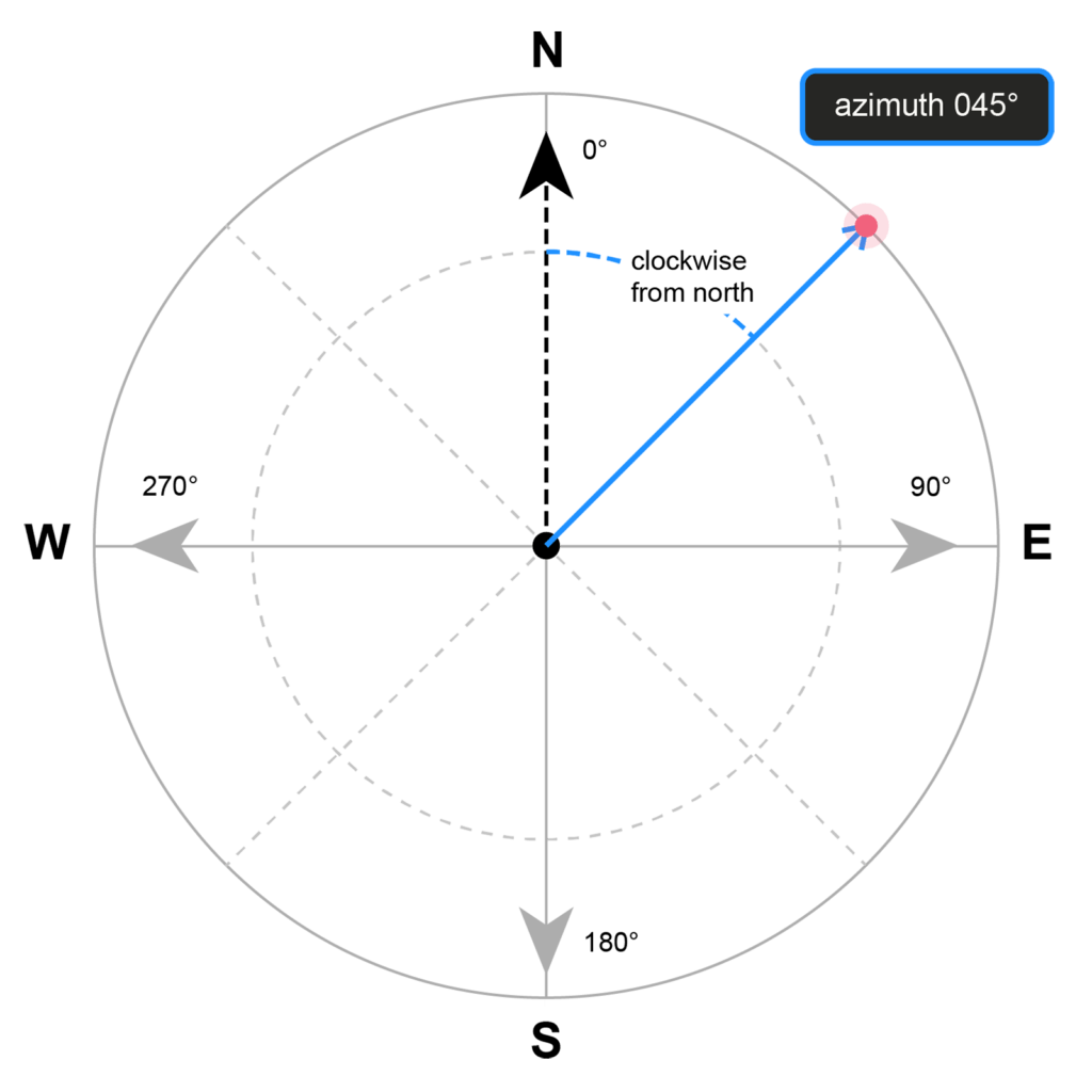
- Azimuth is the precise horizontal direction to a target, measured clockwise from North on a 0°–360° scale.
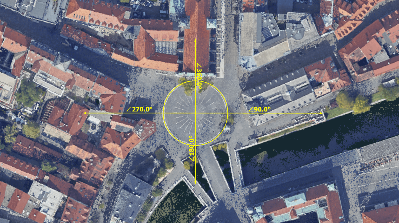
- Cardinal directions are standardized as North (0°/360°), East (90°), South (180°), and West (270°).
- Industry importance spans surveying, drones, aviation, geology, solar, telecoms, construction, maritime, astronomy, and autonomous systems, where directional precision is critical.
- North reference types (True North, Magnetic North, Grid North) must be distinguished to avoid systematic directional errors.
- In 3Dsurvey image processing, drone yaw from EXIF metadata is initially used from Magnetic North for camera orientation.
- In 3Dsurvey CAD measurements, azimuth is calculated from Grid North after georeferencing for coordinate system consistency.
- Measurement accuracy depends on correct drone GNSS/IMU calibration and drawing lines in the intended direction.
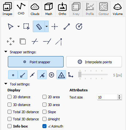
- 3Dsurvey azimuth tool usage requires enabling the CAD azimuth option and measuring toward the facing direction.
- Primary practical applications in 3Dsurvey include solar roof orientation, geological strike and dip analysis, and antenna direction measurement.
What is azimuth?
In case you forgot (or never really needed to think about it) azimuth is just a technical geospatial term for direction expressed as an angle. If you’ve ever worked with maps, drones, CAD, you’ve already used it, maybe without realizing it.
An azimuth is a horizontal angular measurement, expressed in decimal degrees, defining the direction from an observer point to a target, measured clockwise from a defined North reference, spanning the full 0° – 360° arc.
Cardinal reference values
Direction | Azimuth Value |
North | 0° / 360° |
East | 90° |
South | 180° |
West | 270° |
An azimuth of 045°00’00” defines a precisely northeast bearing, unambiguous and reproducible in its expression.
Industries & applications where azimuth is non-negotiable
Azimuth isn’t a niche surveying concept. It cuts across a wide range of professional fields, and in most of them, getting it wrong has real consequences. That’s why understanding it is crucial.
Satellite and telecoms dishes depend on it for precise pointing; a degree off means signal loss. Aviation relies on it for navigation and instrument approaches, and in military applications the stakes are even higher – in ballistics even a fraction-of-a-degree error translates to a significant miss at range. At sea, it has guided vessel heading since the 15th century and naturally carries through to modern sonar and seabed mapping as well.
In geology, azimuth is literally half the story. Strike and dip define rock layer geometry, with strike being a direct azimuth measurement, making it foundational to mining and engineering geology. Solar farm design uses it to maximise energy yield, and construction and civil engineering naturally carry it through every setout, road alignment, and cadastral boundary.
Astronomy, the discipline that first formalised the concept, still uses the azimuth-altitude system as its primary pointing framework for telescopes and radio dishes. And in autonomous vehicles, precise azimuth from IMU and GNSS fusion is what keeps self-driving systems oriented in real time.
Critical distinction: North reference datum
This is where precision matters operationally. There are three distinct North references, and conflating them introduces systematic directional error:
North Type | Definition | Practical Use |
True North | Geodetic North – Earth’s geographic North Pole (top of the globe) | Geodesy, rigorous surveying, most GIS datums |
Magnetic North | Compass North – varies by location and time (magnetic declination) | Field navigation; must be corrected for technical work |
Grid North | North along a map projection’s vertical grid lines | Large-scale mapping; differs from True North via convergence angle |
How is it done in 3Dsurvey?
When drone images are imported into 3Dusurvey the drone’s yaw angle — the camera heading at the moment of capture — is read directly from the EXIF metadata embedded in each image. This value is recorded by the drone’s onboard IMU and compass, meaning it arrives referenced to Magnetic North, together with other telemetry data. It is used primarily to inform the initial image orientation and bundle adjustment, helping the software understand where the camera was pointing during the flight. If your drone GNSS/IMU data is poorly calibrated, this conversion is where heading errors creep in.
However, once your project is georeferenced and tied to a coordinate system, the rules change. When using 3Dsurvey CAD measurements, azimuth is calculated from Grid North, not magnetic north, ensuring consistent results with your CAD data. In other words — 3Dsurvey Grid North is True North projected onto your coordinate system’s flat plane and will always point vertically up.
Mastering the azimuth measurement tool in 3Dsurvey
In 3Dsurvey, azimuth measurement is found under the CAD tab. Select the measure tool and in the Tool settings check the “∠ Azimuth”.
Here is a quick guide on how to use the tool and the top three scenarios of when it is an absolute game-changer.
How to measure azimuth?
Using the tool is incredibly straightforward, but there is one critical rule to remember. The direction you draw your line matters. You must always drag your measurement line towards the direction you are interested in facing, not the other way around.
For maximum accuracy, you can also view and verify your drawn measurement using the top-down ortho mode.
When to use it?
In practice azimuth measurements are most useful when combined with slope steepness information.
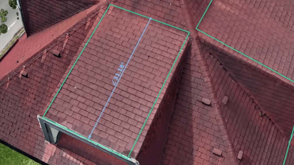
1. Solar Power Plant Planning (Roof Orientation)
If you are planning a solar panel installation, you need to know exactly which way a roof is facing. You can easily find this out by dragging your azimuth measurement straight down the roof’s slope.
Pro-Tip: Combine this with the Plane Lock and Object UCS features! By defining a plane on the roof and hitting the F8 key to lock perpendicularity, you can ensure your measurement is drawn perfectly parallel to the roof slope.
2. Geologic Mapping (Strike & Dip)
In geology, measuring the strike and dip of a rock formation is a fundamental task normally done with a handheld geologic compass. With 3Dsurvey’s RTK videogrammetry and CAD tools, you can easily replicate this digitally. Simply set a custom plane to match the bedding plane of the rock layer, and then draw your measurement line down the steepest point of descent to find the exact angle and direction the layer is dipping.
3. Telecommunications (Antenna Direction)
If you need to figure out exactly which way a cell tower or radio antenna is broadcasting, the azimuth tool makes it simple. Just position your view so you are looking straight down over the top of the antenna, and draw a line pointing outward in the direction the panel is facing.
See examples in our Azimuth measurement tutorial.
Conclusion
Whether you are analysing complex geological outcrops or planning the next big solar grid, this simple tool can save you time and deliver survey-grade precision.
If you haven’t tried 3Dsurvey software yet, you can get a 14-day free trial, with no commitment.