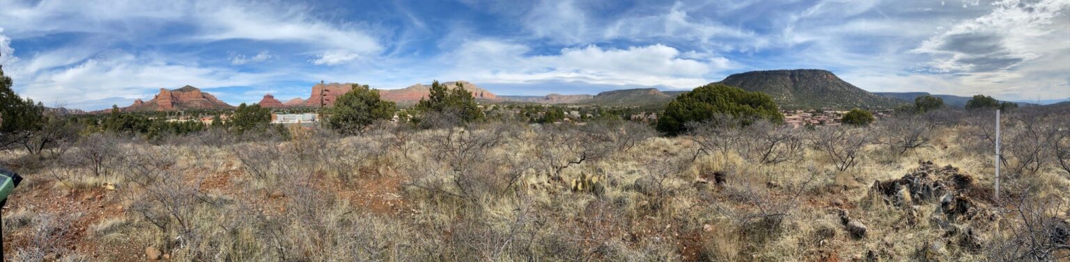
The City of Sedona is located in the desert of Arizona and is surrounded by red-rock buttes, steep canyon walls and pine forests. The area is also well-known as a haven for spiritual wellness due to the numerous energy vortexes that many believe encompass the region. But all these beautiful natural elements also cause some challenges for surveyors.
The City of Sedona and surrounding areas are some of the favorites to work in for Farrah Etcheverry from Etcheverry Land Surveying. She was contracted to make a Drone Topographic Survey for a client who intended to build a house at the base of a mountain. The client required a detailed map for designers and architects, who would design a house matching this beautiful landscape. At the same time she also needed to do a Boundary Survey of an adjacent property.
PROJECT DESCRIPTION
The challenge
The task was to do a Topographic survey and Boundary survey. This would mean that Farrah would need to measure more than 500 points on steep and difficult terrain.
Using a traditional approach, this would involve walking a lot of inclines due to a large elevation difference and big property size. The traditional approach, therefore, would mean a lot of physical labour and would require at least 2 people per day to measure everything properly. There could also be the potential risk that some points are overlooked and not measured, resulting in essential missing details.
Approach
Farrah is an experienced drone and 3Dsurvey Software user and wouldn’t consider doing this job via a traditional approach. That would mean she and her associate would need to spend a whole working day on the field and make sure they didn’t forget any details (not to make another trip back to the field). Therefore the team decided to take a large number of aerial photos using a drone and use 3Dsurvey software to create the orthophoto map and assessments for determining the boundary survey.
SOLUTION
Fast data acquisition
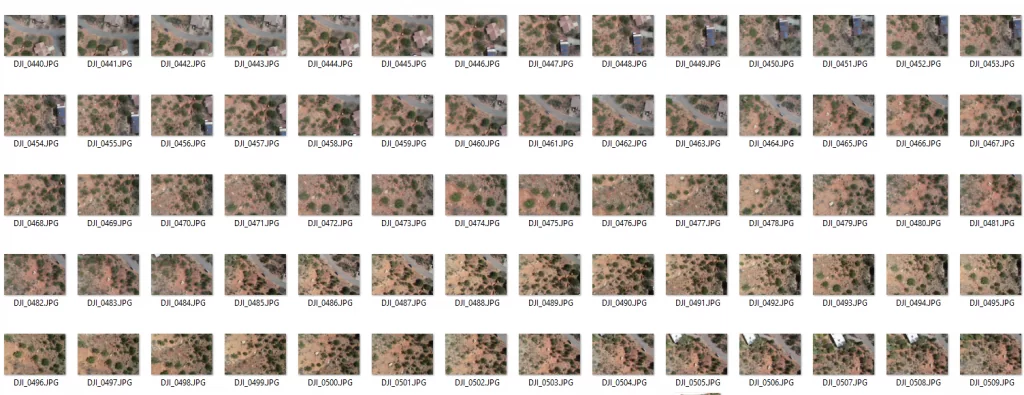
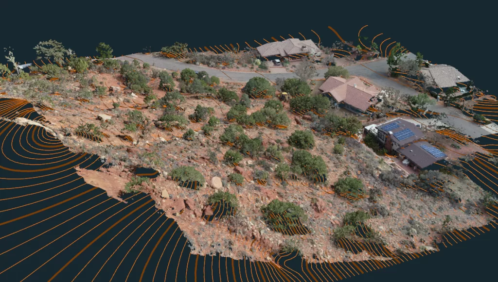
Data on the field was captured with DJI Phantom 4 Pro, and flown with 3Dsurvey Pilot application using the “grid” mission mode. This mode enables the drone to fly automatically with the right settings, and ensures data capturing is safe and efficient. In order to accommodate such a large change in elevation on the property, the drone was flown twice.
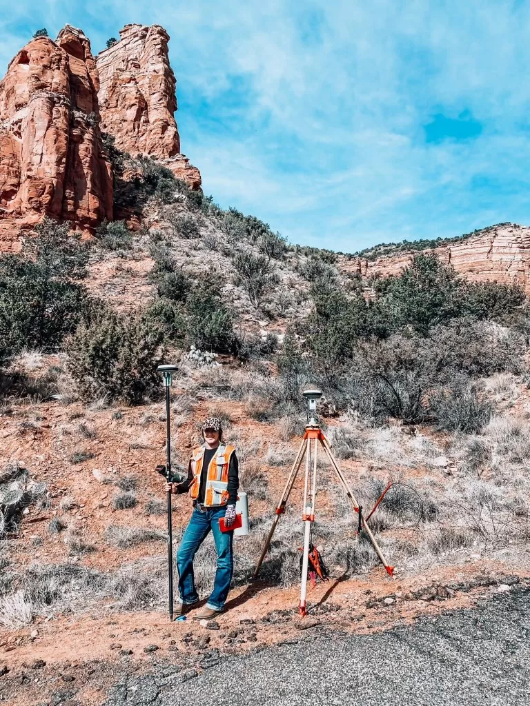
The first flight at 140 ft AGL, and the next at 160, with a minimum of 75% overlap. Because this drone does not have Real Time Kinematic (RTK) technology, a GPS correction technology, GCPs were used for accuracy. RTK tech provides real-time corrections to location data when the survey drone is capturing photos of a site. Instead, 7x 3Dsurvey Ground control Points (GCPs) were set on different parts and elevations of the property.
Project Tools and Specs
Drone: DJI Phantom 4 pro
Ground control points: 3Dsurvey circle targets
Area of Interest: approx 500ft x 500ft
Time in field: approx 4 hours (topo and boundary work x2 parcels)
Location: Village of Oak Creek, Arizona
Processing
For the processing, Farrah followed a simple 3Dsurvey workflow.
Step 1:
- Image import
- Telemetry import
- Select project horizontal and vertical coordinate system
This takes approximately 1 minute and data is already in metadata of the images.
Step 2:
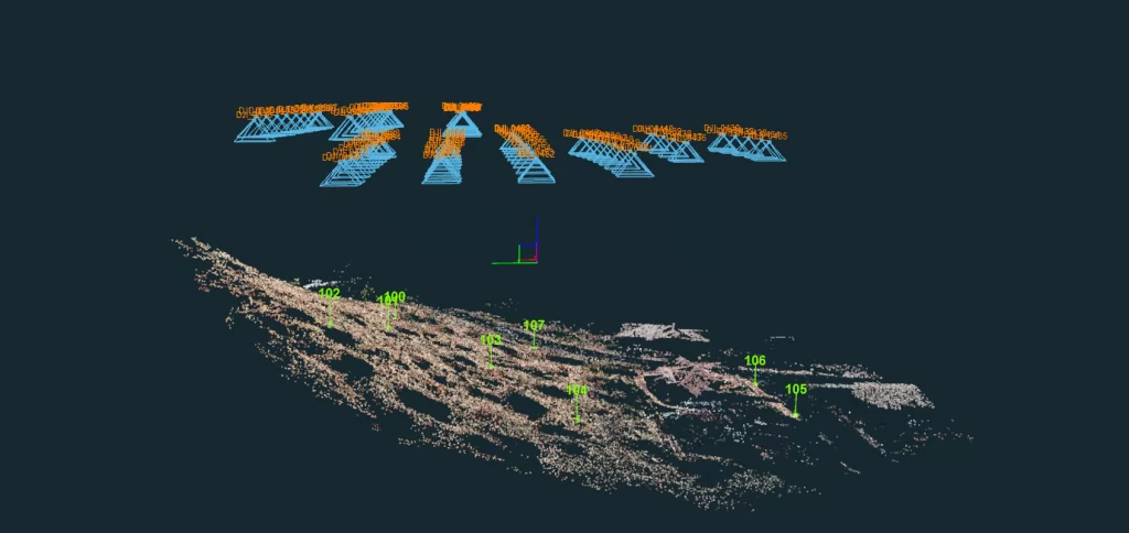
Next is bundle adjustment where the software recognizes and finds common points between images, matches them and generates a raw 3D model – “sparse point cloud”.
Step 3:
The next steps involve:
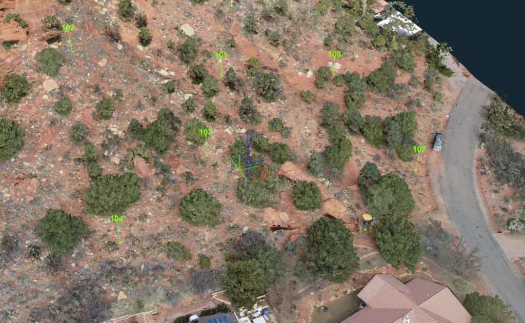
- Automatic recognition and orientation based on GCP measurements with GNSS device from the field
- Locate the GCPs on the images to improve the position of automatic detected targets
- Centering the targets for high accuracy
Step 4:
After orientation, the next step is to reconstruct:
- Reconstruct the model choosing only the density of the reconstruction
The reconstruction step took approximately 2 hours and created a highly detailed 3D point cloud and 3D model of the scene.
Step 5:
From the dense point cloud, the next step is to generate:
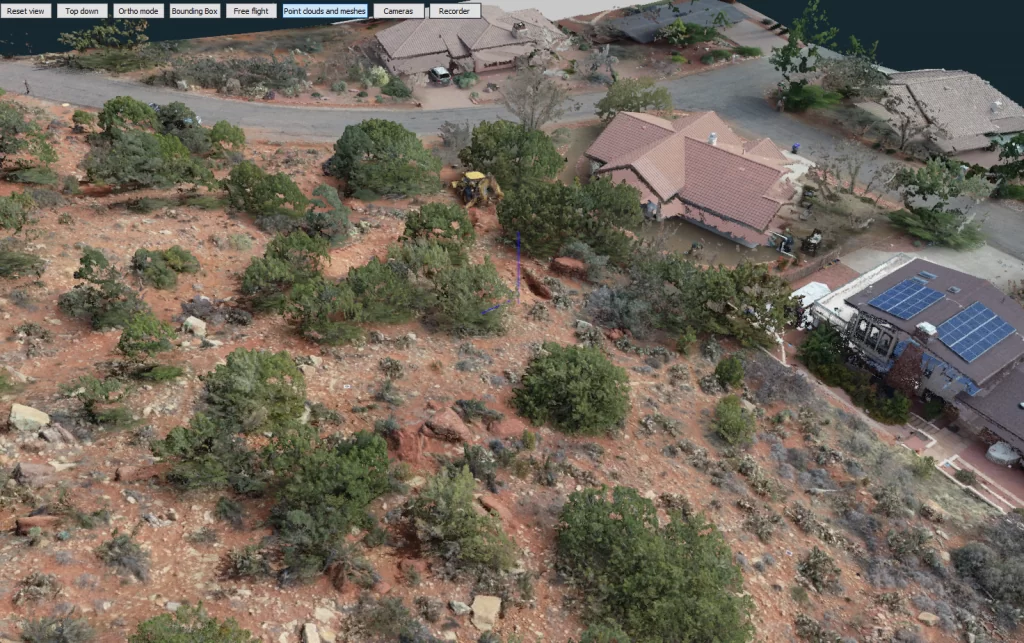
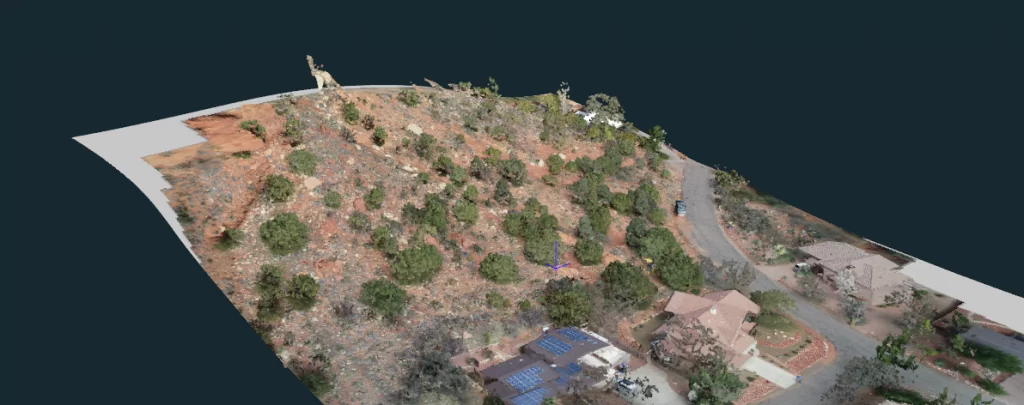
- Textured Full 3D model
A textured 3D model (mesh) is a surface composed of triangles which gives the model a realistic look. If Farrah was using the classical method of surveying – measurements only with traditional surveying instruments – she could not achieve this level of realistic model of the terrain. This realism is helpful to architects and engineers for a better understanding of the project site.
Step 6:
From the textured full 3D mesh:
- Select the desired resolution for the True orthophoto result
True orthophoto gives a vertical view of the earth’s surface, eliminating building tilting and allowing a view of nearly any point on the ground.
Step 7:
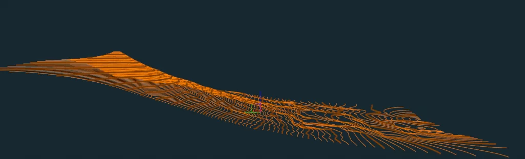
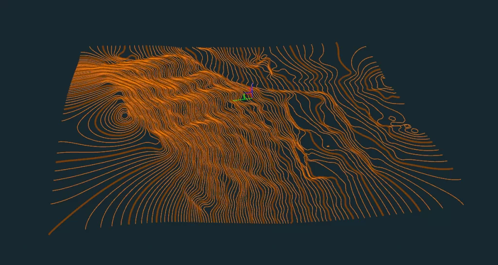
- Add 1ft contour lines for the design team on the True orthophoto
After the work was done, Farrah sent the link to the 3Dsurvey Viewer, so the client could check out the 3D model on their own. In addition to a detailed Topographic map, there were plenty of spot elevations, many of which are able to be derived directly from the 3D data.
RESULTS
- Image acquisition 4 hours – on the field.
- Complete data processing 3 hours – at the office.
Total of 7 hours of work.
Output
- 3D model in OBJ format – standard 3D format
- Orthophoto map in JPG and KMZ ready for Google Earth
- 1 ft contour lines and CAD 3D points and lines in export format DXF
BENEFITS OF USING 3DSURVEY
- Realistic project site visualization ready to be used by architects and designers
- Both tasks (topography and boundary) done at the same time
- No details missed – everything is recorded and ready to be measured
- No need for second site visit if something is forgotten
- Up to 5x less time and costs spent to gather and process data
- Immediate customer access to detailed map
- Possible reuse of outputs for maps and other stakeholders
- Elegant solution (less time on the field, less effort for data acquisition)
Try 3Dsurvey for yourself. Sign up for a 14 day free trial here!