From Mobile Laser Scanning to Complete 3D CAD Documentation
Key takeaways
Two mobile scanning systems combined: The XGRIDS Lixel L2 Pro and FARO Orbis Premium were used to capture detailed 3D data of roads, sidewalks, buildings, parking areas, and visible infrastructure.
Verified survey accuracy: Comparison with GNSS RTK measurements at 20 control points showed a mean horizontal error of 2.2 cm and a mean vertical error of 3.6 cm.
Point cloud processing and CAD workflow: Data from both scanners were processed, georeferenced, and integrated for further CAD work in 3Dsurvey.
Advanced 3D drafting tools: Features such as point snapping, Quick Height Lock, local working planes, and Object UCS supported accurate 3D vectorization.
360° panoramas for verification: Georeferenced panoramic imagery enabled visual inspection, measurements, and feature verification without necessarily revisiting the site.
Reusable digital documentation: The resulting 3D CAD site plan provides a detailed digital foundation for future design, reconstruction, infrastructure planning, and surveying projects.
Project overview
How can an entire settlement be surveyed efficiently and transformed into detailed CAD documentation for future infrastructure and design projects?
In Dobrovnik, Slovenia, mobile SLAM scanning was used to capture the existing conditions of the settlement and create a comprehensive digital foundation for future planning, reconstruction, and infrastructure development.
The field survey combined two mobile SLAM scanning systems: the XGRIDS Lixel L2 Pro and the FARO Orbis Premium. Across eight scans, the systems captured roads, sidewalks, buildings, fences, parking areas, street lighting, traffic signs, visible utility infrastructure, and other relevant site features.
The resulting 3D point clouds were processed, georeferenced, and integrated in 3Dsurvey, where they served as the basis for creating a detailed 3D CAD site plan. This workflow connected rapid field data acquisition with practical engineering documentation, reducing the need for repeated site visits to verify captured details.
The project by Geo-centar demonstrates how mobile SLAM scanning, georeferenced point clouds, panoramic imagery, and direct CAD drafting can be combined to produce reusable digital documentation of an entire settlement.
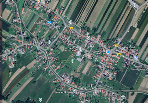
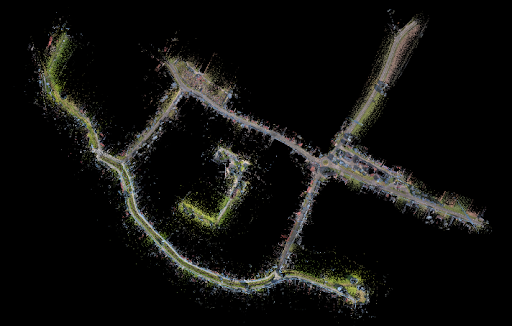
View of the coverage area on Google Maps (left), as well as the merged 3D laser scans (right)
Field Survey
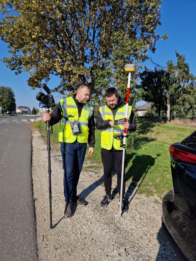
The Dobrovnik site survey was conducted using two mobile SLAM scanners: the XGRIDS Lixel L2 Pro and the FARO Orbis Premium. Four scans were completed with each system, resulting in eight scans in total. Each scan took approximately 20 minutes on average.
XGRIDS Lixel L2 Pro
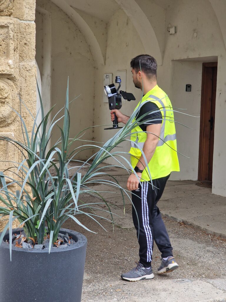
The XGRIDS Lixel L2 Pro is a handheld mobile SLAM system designed for rapid 3D spatial scanning. The system features a range of up to 120 m, an integrated IMU, visual positioning, and an RTK module.
The manufacturer specifies a relative accuracy of 1 cm and an absolute accuracy of 3 cm. The system also includes panoramic cameras that enable point cloud colorization as well as visual recording of the space.
A particular advantage of the L2 Pro system in this project was its RTK positioning capability, which allowed for the direct georeferencing of the collected data.
FARO Orbis Premium
The second system used was the FARO Orbis Premium, an advanced mobile SLAM scanner.
The Orbis Premium enables rapid mobile scanning with a range of up to 120 m and a data acquisition rate of up to 640,000 points per second. The system supports both interval-based and selective panoramic image capture, as well as the recording of very high-resolution panoramas (up to 72 MP).
Additionally, the Orbis offers a static data acquisition mode (FARO FLASH technology), which achieves greater detail and precision.
Unlike the Lixel L2 Pro system, the Orbis does not feature an integrated RTK module for absolute positioning. Consequently, pre-established geodetic control points were used during the survey; the system was positioned directly over these points (using a monopod) while scanning.
3D Point Cloud Processing, Georeferencing, and Accuracy Verification
Following the field survey, data from both systems were processed using their respective software solutions.
Data collected by the Lixel L2 Pro system were processed in Lixel Studio, while data from the FARO Orbis Premium system were processed in FARO Scene.
For the Lixel L2 Pro system, georeferencing was achieved using integrated RTK; for the Orbis system, geodetic control points surveyed during fieldwork were used.
Before proceeding to data utilization, the accuracy of the surveyed data was verified by comparing coordinates obtained via the GNSS RTK method with those from the laser scanning method. The RTK method was used to determine the coordinates of 20 points distributed throughout the settlement (specifically, the centers of manhole covers). The coordinate comparison confirmed the high accuracy of the laser scans: the mean horizontal error was 2.2 cm, and the mean vertical error was 3.6 cm.
After processing, the data from both systems were prepared for integration and further work in the 3Dsurvey software.
3Dsurvey – from point cloud to CAD site plan
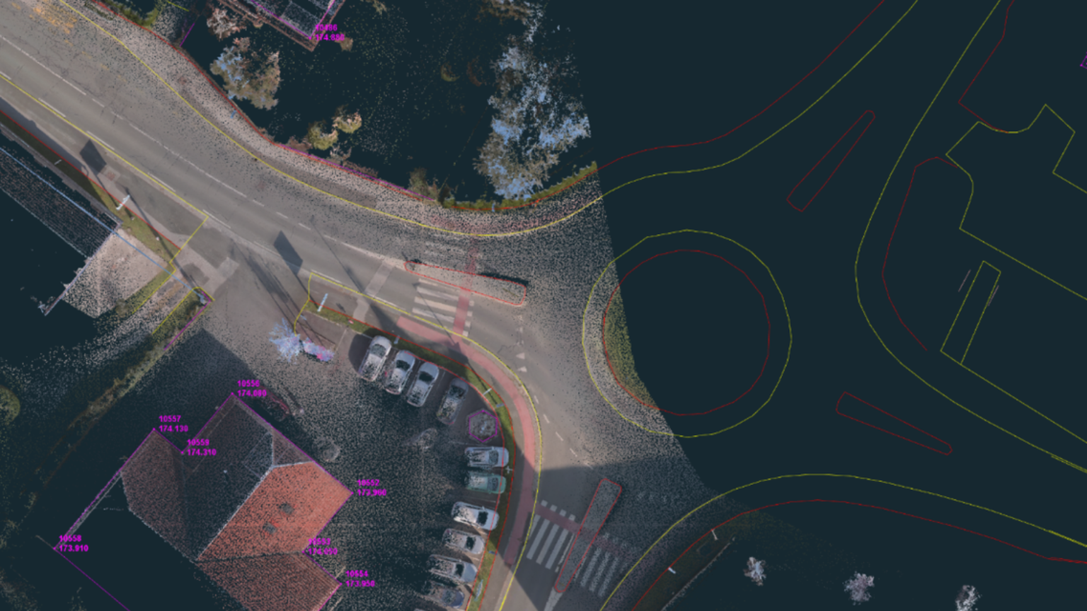
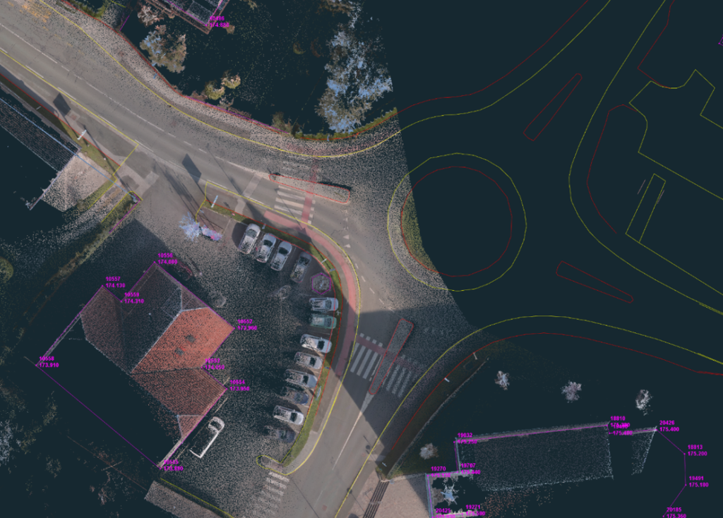
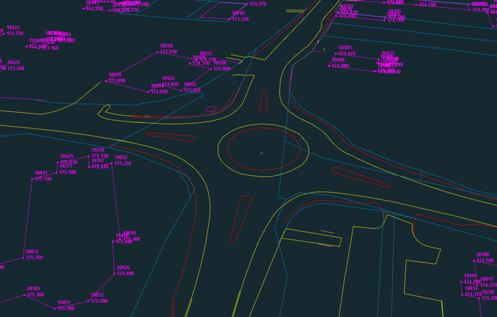
The next step was to transform the processed 3D point clouds into a detailed CAD site plan. Using 3Dsurvey, existing site features were vectorized directly from the point cloud in a 3D environment, enabling the creation of practical CAD documentation based on the surveyed conditions.
A raw 3D scan is valuable data in itself, but its true value is realized when it is converted into a 3D vector model. 3Dsurvey was used for this purpose in this project.
The software enables working with point clouds from various sources, allowing for visualization, measurement, and direct 3D CAD drafting. A particularly practical feature is that the CAD tools operate directly within the 3D view, utilizing actual points from the cloud.
In this way, the point cloud serves not merely as a visual backdrop but as an active foundation for creating the site plan.
In Dobrovnik, various elements of the existing site conditions were drafted from the point cloud, including:
- road edges and curbs,
- sidewalks and parking areas,
- buildings,
- fences and walls,
- poles and traffic signage,
- visible utility infrastructure,
- breaklines and other characteristic terrain features.
CAD functions tailored for working with 3D data
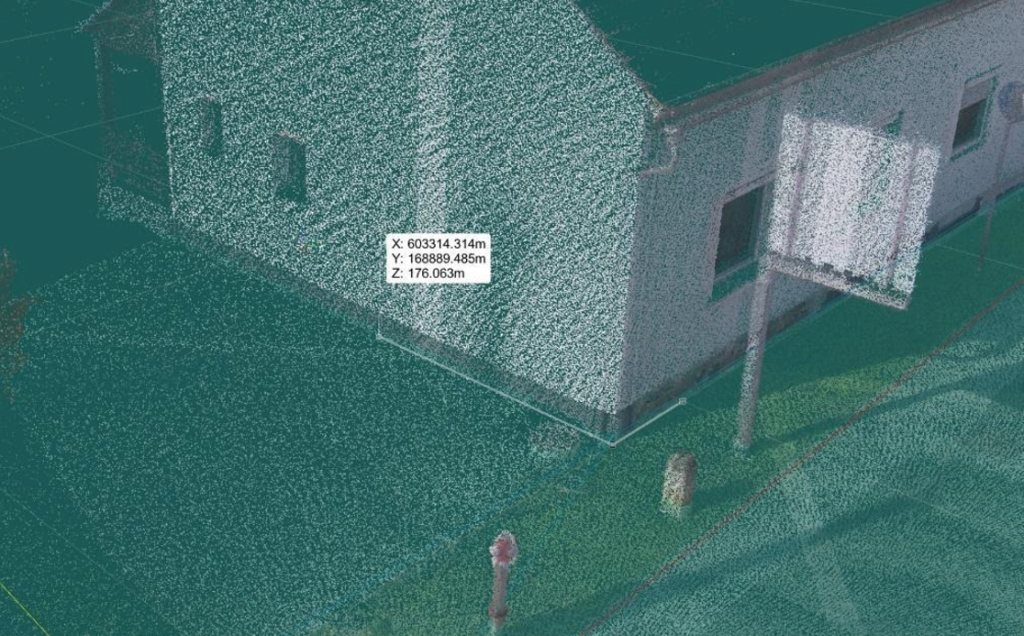
One of the practical advantages of 3Dsurvey is that its CAD tools are tailored for working directly in 3D space.
Point snapping allows for the selection of actual points from the point cloud, facilitating the precise identification of edges and characteristic features.
When creating site plans, the Quick Height Lock function is particularly useful, as it allows for the easy definition of the drawing height for vector elements. Once the height is set, the Z-coordinate can be locked, enabling drawing to continue without unwanted changes in elevation.
For more complex elements, users can also utilize local working planes, Object UCS, and vertical drawing tools.
These features make it easy to draw elements—even those that are not horizontal or conventionally oriented—in their true 3D positions.
360° Panoramas for Point Cloud Verification and CAD Documentation
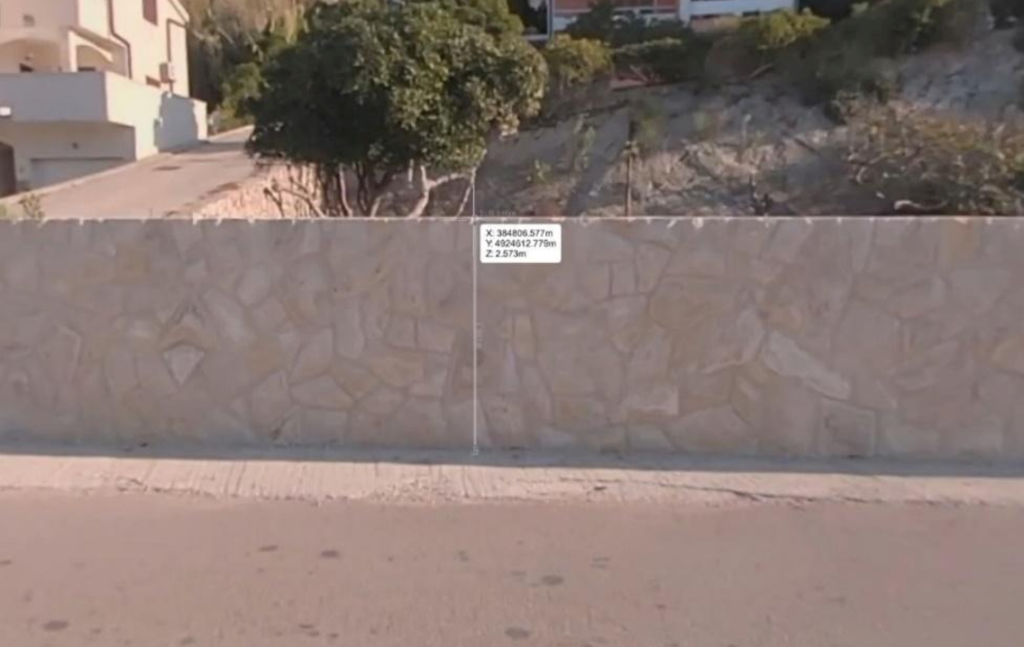
In addition to the 3D point cloud, panoramic photos were also captured during the scanning process.
The 3Dsurvey software allows you to open a panorama from the scanner’s specific position, providing a visual representation of the site as it appeared at the time of the survey.
This is particularly useful when a specific detail is not clearly discernible within the point cloud itself. Instead of returning to the site, you can simply open the panorama to verify the actual appearance of an object or element. Furthermore, since the panoramas are georeferenced, they allow for measurements or direct vectorization.
Consequently, the panoramas serve as valuable supplementary site documentation and a useful tool for quality control when creating CAD site plans.
Conclusion
The Dobrovnik project demonstrates how mobile laser SLAM scanning can support the efficient documentation of an entire settlement. By combining the XGRIDS Lixel L2 Pro and FARO Orbis Premium systems with appropriate georeferencing and accuracy verification, a detailed 3D record of roads, buildings, public spaces, and visible infrastructure was created.
The processed point clouds were then imported into 3Dsurvey to produce a comprehensive 3D CAD site plan. Direct drafting on the point cloud, 3D CAD tools, elevation control, and georeferenced panoramic imagery helped transform the survey data into practical documentation of the existing conditions.
The key benefit of this 3D SLAM scanning to CAD workflow is the long-term usability of the collected data. Rather than serving only as a record of a single survey, the digital site documentation can support future design, reconstruction, infrastructure planning, and subsequent measurement needs.
The Dobrovnik case study illustrates how mobile laser scanning and 3Dsurvey connect field surveying with detailed CAD documentation in one efficient workflow.
Discover how 3Dsurvey can streamline your surveying workflow, from 3D SLAM scanning and point cloud processing to detailed CAD site plans. Start your free trial today and experience the possibilities for yourself.