Surveyors combined terrestrial scanning with total-station measurements to verify anchor bolts and pillar verticality during steel-hall construction.
The Scan module’s X-ray views enabled clear visualization of internal structural elements and precise inspection inside 3Dsurvey.
Integrated CAD tools, top-down views, and orthophotos allowed millimetre-level deviation checks and easy creation of deliverable reports.
Working in one unified environment improved accuracy, reduced processing time, and eliminated tool-switching.
The captured data created a reliable baseline for future control surveys and monitoring structural changes over time.
Introduction
Every construction must be solid, durable and safe. To ensure that, it is required to do many various surveys, not only at the end of the build but also periodically. The scope, specification and frequency of measurements vary depending on the type of structure.
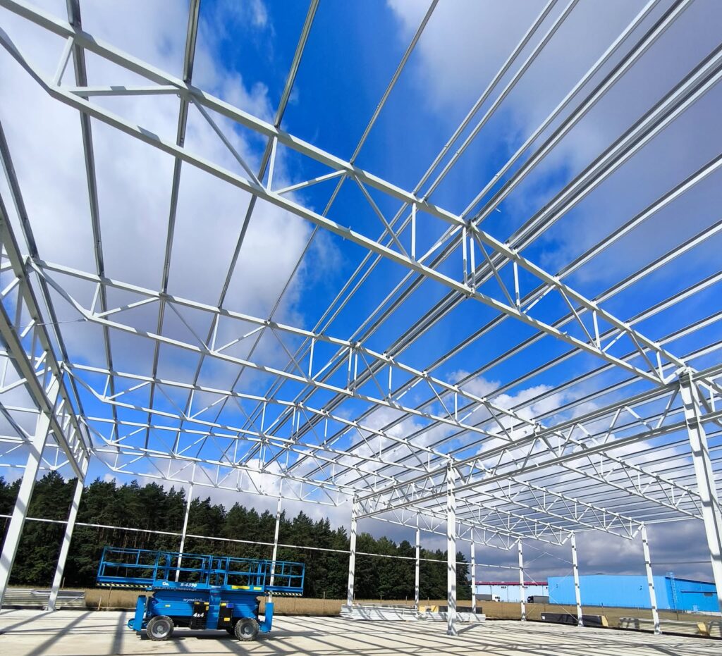
For Geos3D surveyors the latest challenge was to check the verticality of the steel pillars of the future hall, as well as the dimension of the anchor bolts.
After the survey was complete, everything was made in the 3Dsurvey software. The entire Scan module is rich in many necessary functions and options. This time the X-ray views feature came in handy for the Polish surveyors. Everything is in one software, which is perfect for this type of work.
The results will later be used as a basis for the future control surveys. This makes it easy to show how quickly changes are progressing.
Approach
In the field
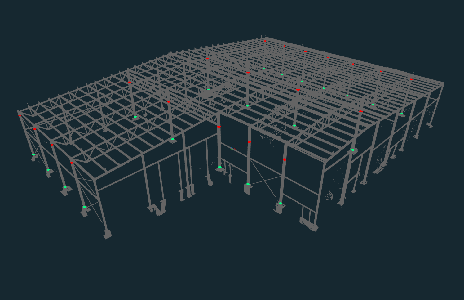
The entire object of the project.
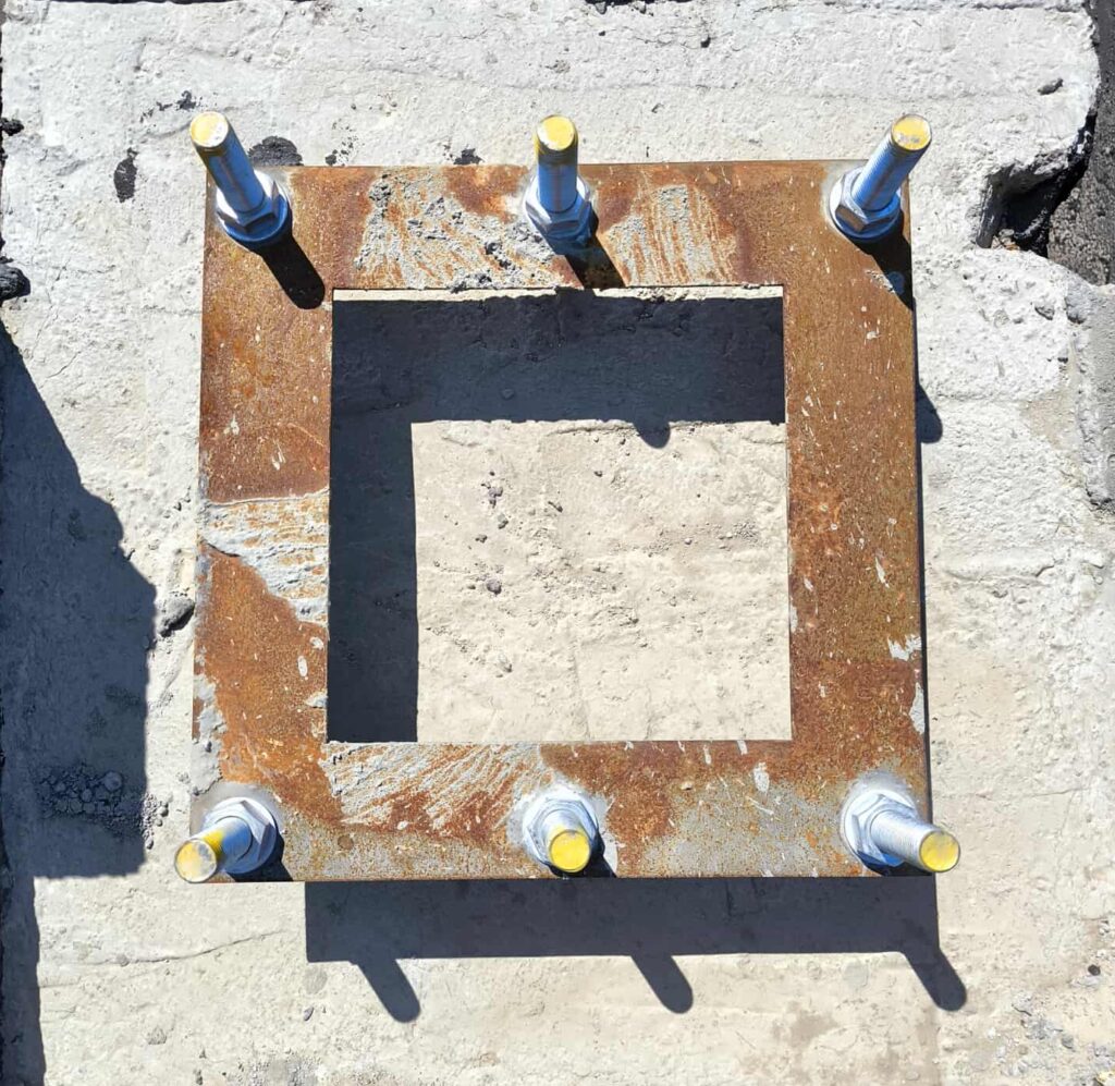
The anchor bolts from the project.
The fieldwork included terrestrial scanning and survey using Leica RTC360 scanner and MS60 total station. The combination of these two methods was the best way for them to quickly and accurately obtain the 3D digital representation, which is the basis for subsequent stages of the control surveys.
The surveyors were on the field twice:
The first time when only the concrete base with anchors was there. The total station was used to measure the centres of the anchors with the highest accuracy and precision.
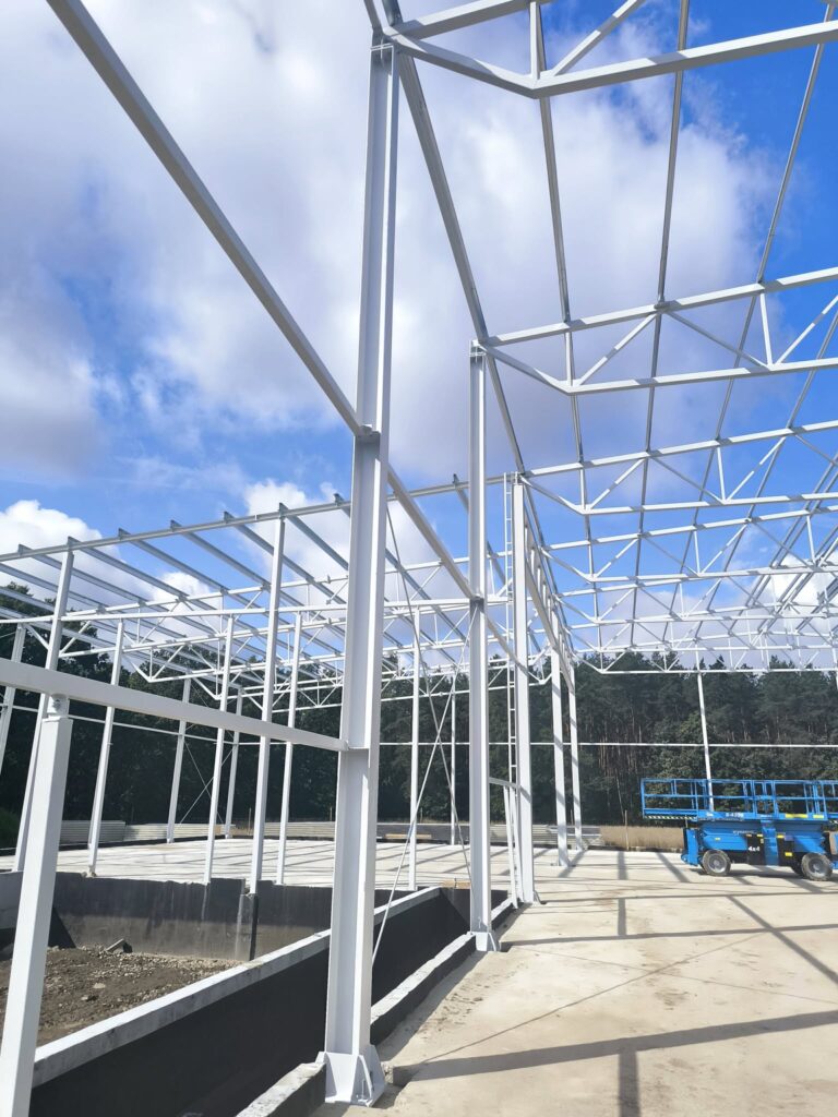
The second visit was after the I-beam shaped pillars had been installed.
I-beam shaped steel pillars.
In the office: Processing in 3Dsurvey
The work was divided in two parts:
The first one focused only on the anchors
The second part was about pillar verticality
That means the point cloud was needed twice as well, separately for both parts. This was done using the Bounding Box, Select, and then Delete tools. During this process, it sometimes happened that the area selected for deletion was too large or something they did not want to delete was accidentally selected. For these cases the software has a Deselect option available, that works similarly to Select. Thanks to this, everything was fixed very quickly, without any major negative effects or wasted time.
1. Placement of anchor bolts
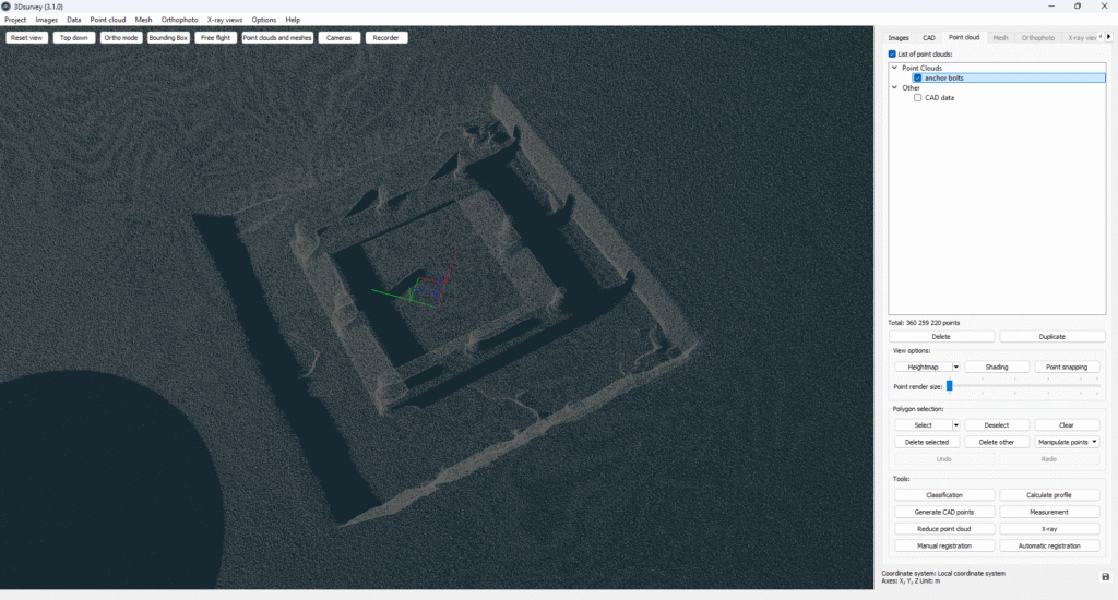
Points imported from direct survey measurements using a total station into the 3Dsurvey software implemented a point cloud. This allowed for double verification of the data.
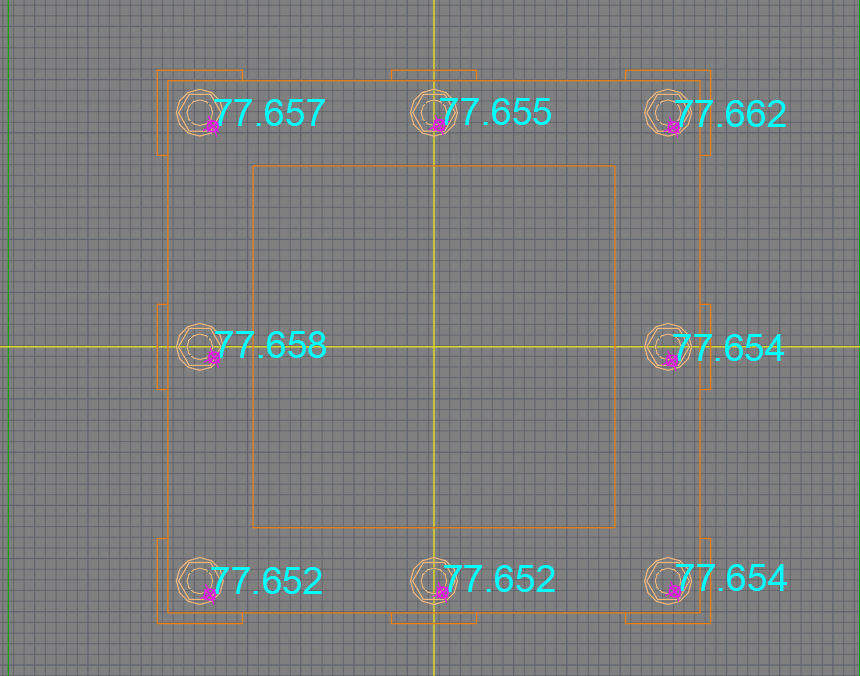
Additional points, especially point heights, were added at the top of the bolts. Another great option in 3Dsurvey is the ability to adjust the number of decimal places in the application settings, which is a feature of the version 3.1. This is crucial in this type of work, where every millimetre counts.
Scanned anchor bolts in 3Dsurvey.
Comparison of the designed anchors and results of the survey.
2. Verticality of pillars
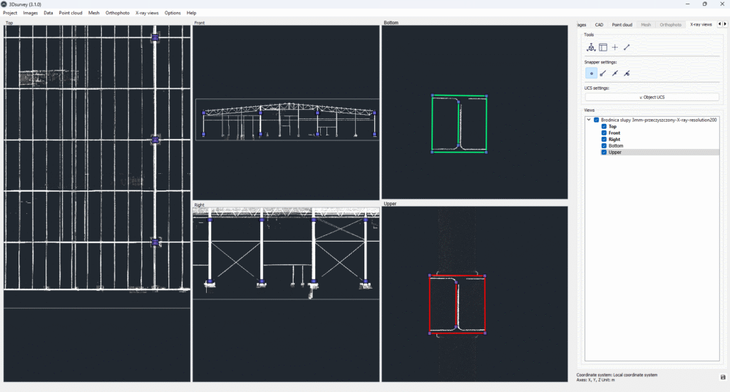
To measure the verticality of the pillars, the X-ray views was created. Two views were needed, one at the top of the poles and the second near the concrete floor. In addition, two more layers in different colours were added to the CAD tab – for the upper and lower parts. The active layer in CAD tab had to correspond to the selected X-ray view.
Then the best part began. All there was left to do was to draw the actual lines of each I-beam cross section. The auxiliary lines were added to close the shape in a square. Snapper settings were really helpful to draw everything without undesired spaces between the lines and points.
The same process was repeated on the other ends of the pillars, but on the different layer and X-ray view.
X-ray views on both levels in 3Dsurvey.
At that time, everything was clearly visible in the main views – every step could be controlled in real time. The workflow in 3Dsurvey software was impressive as always.
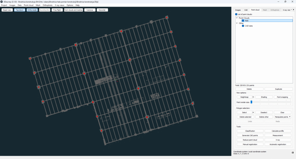
Another option that helps control the process is the Point Cloud tab, where you can activate the Top Down and Ortho Mode buttons. These enable you to see the structure without perspective, which is extremely helpful for this type of projects.
Top Down and Ortho mode in 3Dsurvey.
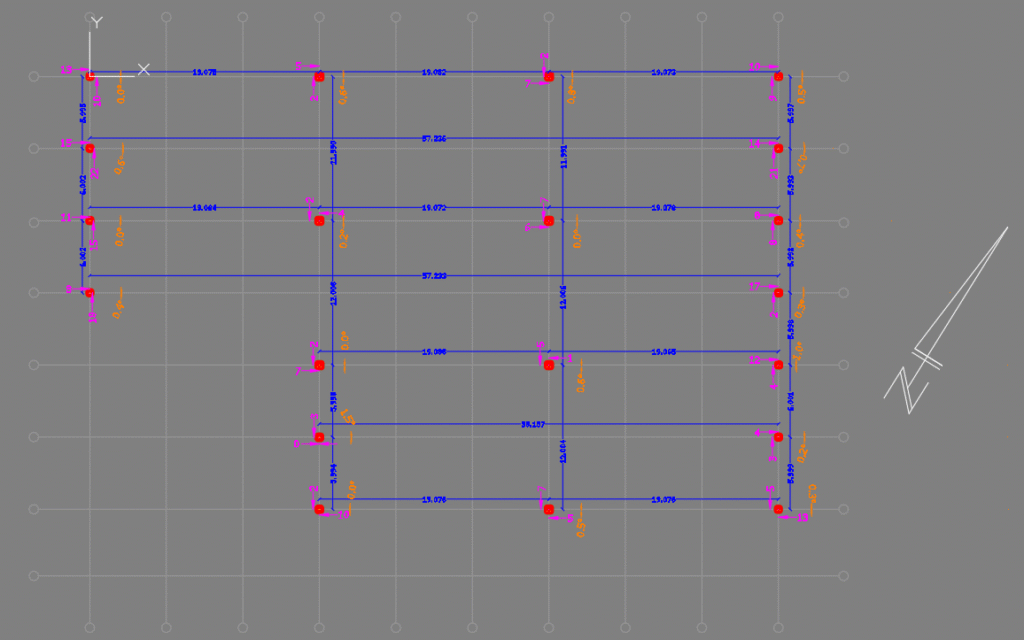
After that, when they had a cross-section of each I-beam and its accurate position, they could export CAD data and measure the deviation and rotation.
In the CAD tool, it was just a final touch to measure it.
The entire structure with measured deviations and rotations of all pillars.
Conclusion
3Dsurvey software allowed surveyors to quickly process point cloud with incredibly high accuracy. This type of work has to be done precisely as every mistake could mean a high cost of the collapse of the structure. Additionally this measurements will be used and compared with control surveys in the future.
For that X-ray views, which is part of the Scan module, was irreplaceable. Without this feature, the project would take a lot more time and energy.
Have you used our Scan module yet? A monthly subscription provides you the flexibility to use it when you need it. Enhance your scanning and integration capabilities and save time!