Drawing building outlines using 3Dsurvey’s advanced CAD tools
Key takeaways
Advanced CAD tools allowed drawing building outlines from drone data even on a cluttered, obscured site.
Height-lock, custom drawing planes, and perpendicular snaps made tracing walls, roofs, and features fast and precise.
The integrated CAD engine with top-down, ortho, and 3D views eliminated guesswork and manual adjustments.
Complex architectural elements like overhangs, balconies, and hedges were mapped accurately with minimal field revisits.
The workflow is built by surveyors for surveyors — enabling efficient, reliable deliverables from raw imagery to vectorised outlines.
Introduction: New CAD tools make mapping easier
We’ve all been there. You arrive on site, ready to map a building, only to find it half-hidden behind trees, surrounded by hedges, cluttered with obstacles, and its walls obscured by balconies and roof overhangs. Sound familiar? Don’t worry, with careful drone work and a few well-placed control points, you can collect everything you need. Once you’re back in the office and your data is processed, that’s when the CAD tools come into play – helping you to vectorize building outlines and produce clean, accurate drawings. But how do you turn messy field data into clean, usable geometry?
The Task: Define a building outline using CAD tools
The task was to define an accurate building outline for cadastral registration. The challenge was to include those hard-to-reach corners, obstructed views, and overhanging elements. With a classical approach, this would be a nightmare, and you’d be happy to pull off all the measurements in a single day of field work.
Modern drone mapping combined with the newest CAD tools from 3Dsurvey brings precise height control, plane lock, perpendicular lines and smart snapping that makes this not only possible but highly efficient.
Our Site: A real-world challenge
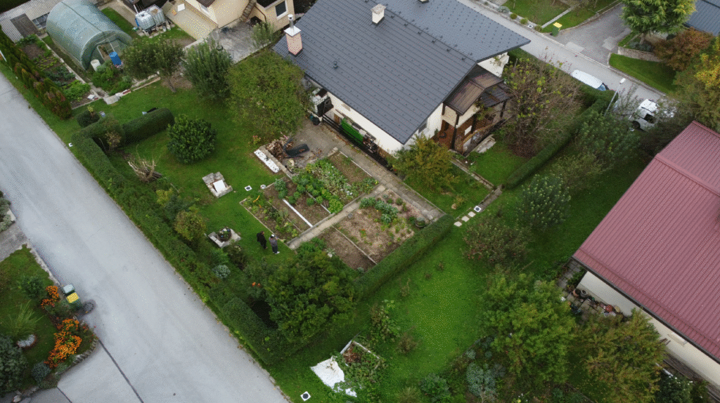
The site was a residential house fenced by a hedge, a garden behind it and plenty of trees for shade, some reaching the roof. The house had a balcony and a few overhangs. There were some areas where materials were being stored. The terrain was a gentle slope, and there were a few other obstacles and irregular features. This is an example of a classic countryside home.
Drone photo of the site.
Approach
The field
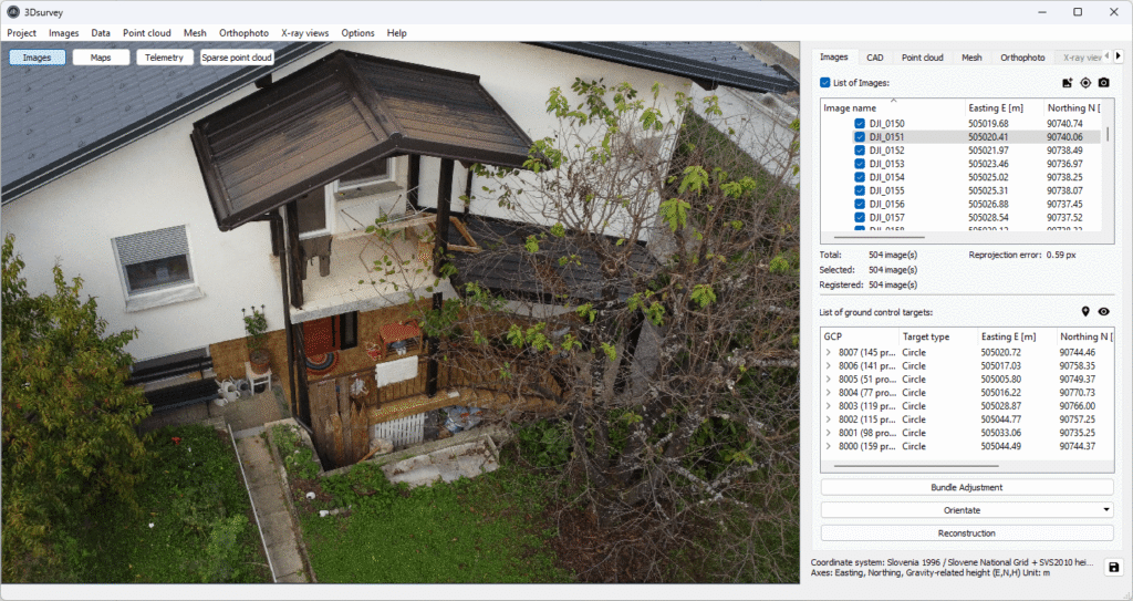
With a drone, the site was documented with 500 images in top-down, oblique and circle paths. Several control points were measured using GNSS. Since the drone lacked the RTK antenna, 8 GCPs were used to ensure surveyor-grade precision.
Since the drone lacked the RTK antenna, we used 8 GCPs to ensure surveyor-grade precision.
In the Office: CAD Tools in Action
The images produced a good, dense point cloud. However, for this task, we were going to need the full power of 3Dsurvey’s integrated CAD tools.
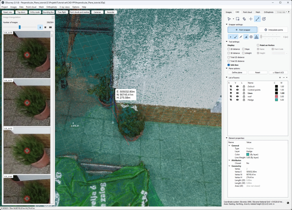
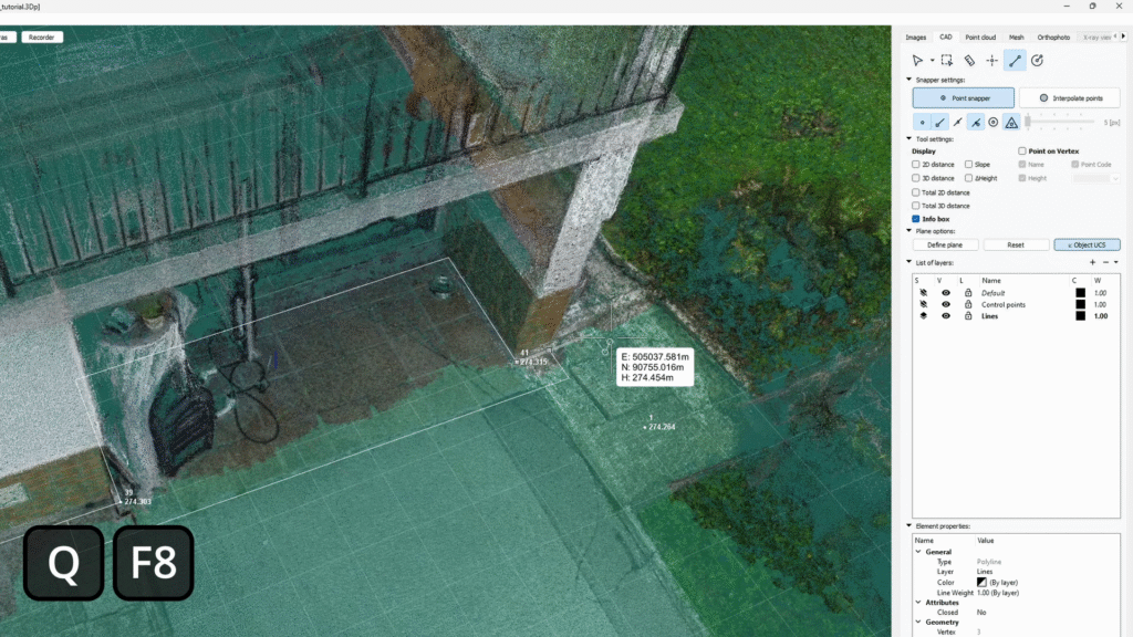
We started simply and systematically by importing the control points from the field, then creating a new vector layer dedicated to the building outlines. The control points can be used to lock height using the Q key: position the cursor over the chosen point and lock it by holding down the Q button. Anything now drawn in the CAD engine will be locked to that height.
Because we wanted to have our building outline on surface level, we needed to project the line where the edges protruded the most – down to the ground level. It used to take painstaking triangulation and manual height tweaking, with no guarantee of accuracy. Now, with 3Dsurvey’s tools, it’s fast and straightforward. Image side-pane offer an additional visual check of the point’s position.
We used point 4 as an “height anchor”, while the horizontal location of the corner is defined by the protruded corner.
Building outlines with CAD Tools
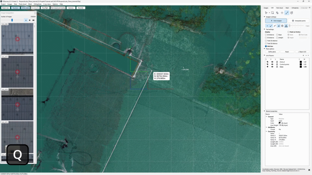
We began tracing from the outermost building corners, projecting wall edges downward, no guesswork needed. The height-lock was quickly adjusted on uneven surfaces with the push of a button. To visualize our accuracy, we switched to “top-down” and “Ortho” view.
For complex areas like balconies, a bounding box lets you crop out the roof and gain a clear view.
Combining Top down, Ortho mode with quick height lock to double-check precision.
Perpendicular Lines
When drawing CAD lines on a plane, you can take your accuracy to the next level by locking your lines to be perpendicular to an axis you define. When it comes to drawing building outlines, this CAD tool is a game-changer. The quickest way to activate it is to hit the F8 button while holding down Q. While quick, this shortcut can be tricky to execute smoothly during drawing. Good news? There’s a cleaner way to do it.
3Dsurvey 3.1 introduced the height lock - Q and Object UCS - F8 (perpendicular lock).
Adaptive tools for real-world problems
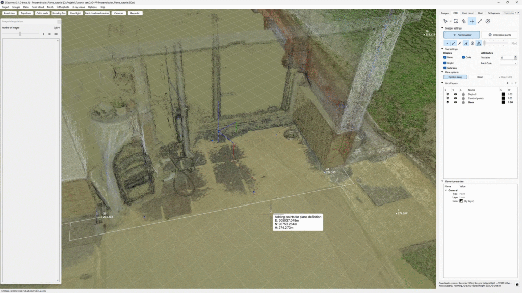
Some surfaces aren’t even and/or easily accessible. In this case, we were dealing with a slightly sloped area under the balcony. To get around it, we defined a custom drawing plane:
Click “Define plane” in the “Plane options” of the CAD tab. The info-box reminds you that you are now placing points for the plane definition.
Place points to define the plane.
A yellow grid plane appears when you are done placing points. Confirm it by pressing “Confirm plane” or right mouse click.
Define a custom plane: use 1 point to ensure it’s horizontal, otherwise use 3 points or more.
Now all the CAD work will snap to this custom plane. After drawing the first line, you can take it a step further by activating Object UCS, effectively locking in perpendicularity.
Navigating Clutter with CAD Tools
Getting around the cluttered corner still isn’t easy. How do you know where the actual corner is if you can’t see it? That’s where Object Snap Tracking comes in.
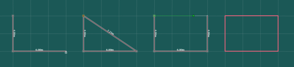
Stages of activating an Object Snap Tracking:
Confirm a second line segment (third vertex)
Move your cursor over your target vertex (but don’t click)
When finishing the third line segment, the green leading line appears, and confirm the fourth vertex
Finish the polyline with precision
The combination of perpendicular lock (UCS), leading lines, and image-based retriangulation helps to handle tricky zones with confidence. Using these tools you are able to complete the wall tracing all the way around the house. Now we could draw more with less data because we could carry-over the information with the height lock, ensure perfectly perpendicular lines and submit accurate results.
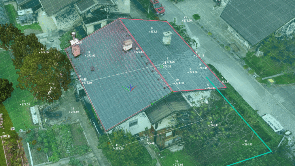
Roof Vectorization and Vertical Features
Moving to the rooftop, after creating a new layer, we defined sloped planes by placing four points and started drawing lines. Hitting F8 after the second vertex locks Object UCS, allowing smooth continuation.
When drawing the adjacent roof slope, reuse vertices from previous planes for perfect intersections and clean vector continuity.
With these CAD tools, even roof surfaces with challenging angles or alignment issues become manageable.
Final Touch: Tracing Hedges and Ground Features
Even traditionally cumbersome tasks like hedge-line mapping are simplified. Just two clicks (one on each side of the hedge) and a press of the Q button lets you lock your elevation and trace the midline with ease. What once took time and manual tweaking is now straightforward and reliable.
Grab a height point you need and lock it with the Q button.
Conclusion: CAD Tools Built for Surveyors
Developed by real surveyors, these CAD tools are built to solve the real-world challenges we all face. With height lock, custom planes, perpendicular lines and snapping, you can draw clean building outlines faster, with more control and precision. If you want to explore more about our integrated CAD tools, read our blog post.
You can also check out the workflow in the video tutorial. Don’t forget, we offer a 14-day free trial of our software. Don’t wait around, try it out for yourself.