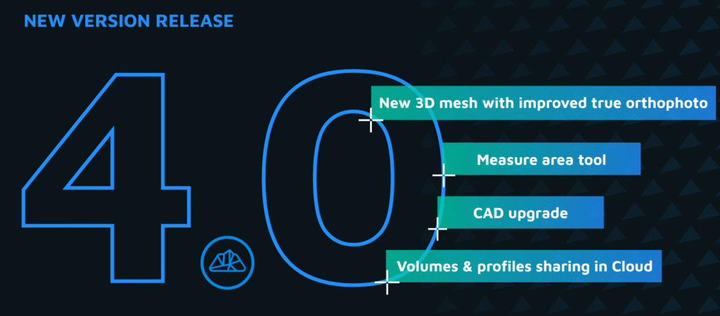
What Is CAD on Mesh Projection?
The CAD on Mesh Projection feature in 3Dsurvey enables users to accurately align 2D CAD data—such as cadastral plans, DXF drawings, or architectural layouts—with 3D mesh surfaces. This is essential when working in a 3D environment, as imported CAD data typically defaults to an elevation of zero and may appear beneath the terrain or model.
Why Use It?
Projecting CAD elements to the mesh surface automatically adjusts their vertical position to match real-world elevations. This ensures that lines and points fit correctly on the 3D model, making it possible to analyze, visualize, and edit data with accuracy and confidence.
How It Works
With just a few clicks, users can select any CAD layers and project them onto the chosen mesh. The elevation of each point or line is recalculated based on the mesh surface below (or above), ensuring a perfect spatial match. For complex structures like roofs or steep terrain, you can even choose to snap CAD elements to the highest point of the mesh—ideal for avoiding placement under overhangs.
Practical Applications
Cadastral and Land Surveying: Visualize boundary lines directly on terrain models.
Architecture and Roof Design: Place solar panel layouts or building outlines onto roof surfaces.
Construction and Earthworks: Align selection polygons or design elements to terrain for accurate volume calculations.
Enhanced Visualization and Inspection
Once projected, CAD elements become fully integrated with 3Dsurvey’s visualization tools. You can:
Snap to vertices and surfaces in 3D
Inspect elements using the “Drawing on Images” tool
Adjust geometry precisely in 3D space
Important Notes
Be mindful of the mesh edges. If CAD elements extend beyond the mesh boundary, they may be assigned an average height instead of following the actual surface. For best results, ensure your mesh covers the entire area of interest.
For further support, feel free to visit the 3Dsurvey forum or contact the support team at support@3Dsurvey.si.


