
Creating an orthophoto of a round tower
For this project, our user, Mate Denona, needed to create a custom plane orthophoto of the inner and outside walls of a round tower. Read his challenging process below.
1. Terrain reconnaissance
After the work was agreed upon, I went to the field to come up with a plan. I arrived at the foot of the hill by car – the thermometer showed 37 degrees Celsius. This was followed by a sweaty climb up the hill on foot and planning the flight time.


Mate was happy to be working outside in this perfect weather. Or was he? Read on to find out.
The object is circular in shape and I concluded that there would be a problem with the photogrammetric model and shadows unless I did the shooting at the same time of the day each time – around 12pm. This would be an unnerving task to do in the midday heat though. I looked at the terrain and concluded that for my health, I would postpone the work until the temperatures started to drop, at least to a maximum of 30 degrees.
2. Setting the geodetic base
In the early morning hours of my selected field day, I set out to develop a geodetic basis for photogrammetric recording. There were two of us onsite. We carried a GPS, a total station, sprays, painkillers, glue, pre-prepared marks for reference points, and fire ladders.
With the help of GPS and the HR NTRIP System, CROPOS, 2 sets of ground control points (1001 and 3001) were set up in line of sight around the area of interest – the tower.

The GCPs were created by hammering down bolts and marking them with a red spray so that they were easier to see when flying a drone.
After that two sets of ground control points (1002 and 2001) were placed inside the tower.
Four sets of targets were also placed on the walls of the tower. 1201-1210 were placed on the outer wall of the tower, and 1101-1108 on the inner one.

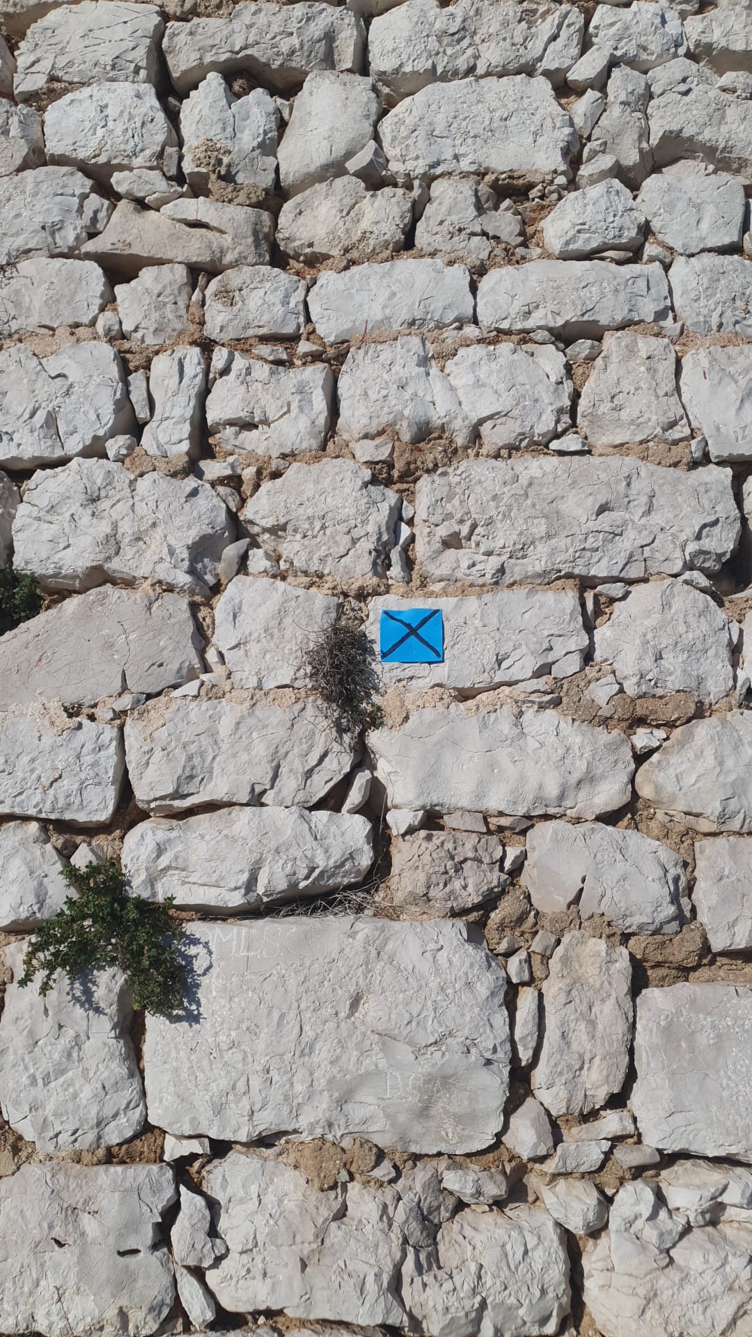
Two examples of the wall marks.
A total of 22 GCPs were placed, measured with a total station.

While we were setting it all up, it started to get unbearably hot again, and we decided that the smartest thing to do was to look for some shade in the nearby town of Stankovci and charge our batteries for the afternoon, recording the set points with a total station.
We returned in the afternoon when the temperature had dropped slightly and determined the coordinates of all GCPs. At dusk, exhausted, but satisfied with the work done, we descended the hill to the car and went to a well-deserved dinner.
3. First drone recording
Although the idea was to wait for a cloudy day when the refraction of the clouds would wipe out the shadows and thus enable us to shoot for a couple of hours without changing the lighting, due to the project’s deadlines, I decided to take a chance with the drone. I arrived at the position at 10 am on the day. The equipment used was DJI phantom 4 pro V2.0 and I carried 9 charged batteries with me.
With the help of the 3D survey pilot app on the mobile phone, I went on the first flight mission. I made a grid of the area of interest with 85% Front Overlap and 82% Side Overlap and 35m height with a double grid.

Then there were 10 circular missions around the tower to photograph the outer wall, and finally manual flying inside the tower itself, where 15-20 pictures were taken in a circle every half meter of height downwards.
At around 2 pm, the batteries were empty and my concentration was low due to the summer heat – I couldn’t wait to put the data into the computer.
In total 1910 images were taken.
I had confidence in my hardware and software to manage the data.
Tools
Hardware: Dell precision 5820 tower, CPU: Intel Xeon W-2195, RAM 256GB (ecc ddr4), GPU 2xNvidia RTX A5000, ssd: NVMe samsung 970 PRO.
Software: 3Dsurvey
Workflow
I did Bundle Adjustment and it finished in about 10 hours. Later I realized that the photos where you can see far around, as well as the photos that have distorted positions in the EXIF file, cause a problem (photos of the inner walls of the tower).
The result, however, is a beautiful point cloud.
I did the orientation and everything still looked perfect. From the textured mesh, I extracted the orthophoto, played around a bit and then was done!
I deleted the excess points of the point cloud and left the computer to calculate the full 3D mesh (as it was still extremely hot, the computer was outside on the balcony overnight)🙂

The mesh calculation finished, and while everything was being calculated, I figured out how to cut the tower into 8 parts in CAD and downloaded those coordinates to calculate the custom plane orthophoto of those circular sections.
However, the mesh tower was not of satisfactory quality for what I had in mind. The problem was that the images I had taken were overexposed. After some brainstorming, I realized that I would have to go on a new flying mission.

4. Second drone recording
I decided to start again with the knowledge I had learned so far. This time, I decided to fly manually about 4 metres from the tower itself. This was done to help the software be faster with the calculation.
I flew only the outer walls with all the batteries I had. This was done in a way to “scan” those parts of the tower during the time of day when they were not exposed to direct sunlight. This was to avoid overexposure of the images again.
Bundle adjustment was done quickly, even though I had a mass of data. It took roughly 4 hours and then I did the orientation, and I left the computer to calculate the mesh.
I could breathe a sigh of relief, as the mesh is outstanding! I would do the same with the inner walls!

I dedicated my attention to creating custom plane orthophotos of the outer wall, and everything looks great! I planned an upcoming mission to shoot the inside of the tower as well, because finally a cloudy day would be smiling upon me. 😊
In CAD I calculated the position for the custom plane orthophoto. I entered it in 3DSurvey and everything went smoothly. For each plane I carefully entered the coordinates and quickly got 8 perfect orthogonal projections of circular slices of the outer walls of the tower.

5. Third drone recording
By now I had devised a proven method. The flight was not problematic and the processing went smoothly. I produced the inner wall without error.
I used the Bounding Box to get horizontal and vertical sections.


Working with the bounding box tool.
For the horizontal section, I extracted the points from 3Dsurvey and drew them in CAD. For the vertical section, I first calculated the line in CAD, which I inserted into 3Dsurvey. Then on the classified DSM (deleted trees and unwanted elements) I drew a profile – which I processed again in CAD.
When all the custom plane orthophotos were created, I used them in the final report. The report depicts each section of the wall from inside and outside.

Another very handy aspect of working with 3Dsurvey is the ability to upload the entire project to the cloud. This way I was able to share it with other people, even with those who don’t use the software or aren’t at all familiar with the concept of photogrammetry.
Thanks to Mate for this interesting use case about how to tackle creating a custom plane orthophoto of the walls of a circular structure. It took some trial and error, but we think his method works well!