Basic 3Dsurvey workflow: True orthophoto
Welcome to the general 3Dsurvey workflow tutorial.
In this tutorial, you will learn the whole process of creating true orthophoto from importing images to classifying point cloud and calculating 3D mesh.
Watch it on YouTube:
Workflow
First, we need to import our images into a new project. To do this, we click on “New Project” and then select all the images by holding down the “Ctrl” and “Shift” keys and selecting the first and last image. Then we click “Open” to confirm our decision.
Next, we need to select the project coordinate system and the vertical coordinate system. In our case, we will be using Slovenia 1996 and EGM 96. In the telemetry importer, UAV model, we also select the EXIF data as most DJI drones write information this way. To confirm our decision, we click “Import”.
When telemetry is imported, we are automatically shown some technical information about the images, including the accuracy. We can also view the telemetry information by clicking on “Telemetry”. This will show us how the drone was flying and where the camera was pointed.
The next step is bundle adjustment, which we can select by clicking on “Bundle Adjustment” on the lower right part of the screen. We choose global mode, as it is the fastest and most stable. We will usually have to wait about 10 minutes to get our results.
Once the bundle adjustment step is finished, we can see our sparse point cloud which connects our images. The next step is orientation. We click on “Orientate” and choose orientation with GCP data. Then we import our GCP file and select known-projection since we used an RTK drone and have the right coordinate systems. When we click “import” we will be taken to a new window where we can configure each target. Click “Next” and we come to the orientation wizard.
The first thing we see in the orientation wizard is our first image, list of images and a mini-map containing the ground control points in the top right corner. Here we need to find our first ground control point, click “Next image” until you find it. After spotting it, we zoom in by using the scroll wheel, and we will see an actual target and a green circle representing the estimated position of the target. We will also see a number, which shows us which ground control point this is. If the circle is not already on the target, we must click the number of the target on a mini-map with a left mouse click and then also click the middle of the target with a left mouse click. By doing this, we have improved our position of the first target. We repeat this process for each target, ignoring any targets without a green circle.
Once we have found at least three targets, the program will automatically detect the position of all other targets. Now you can check if the targets are aligned with the green circles, but usually no additional user input is needed. Make sure that “Detect GCP targets” box is checked. We then click “Next” and wait for our GCPs to be detected.
Now we are sent to the detection overview, where we center the targets. Notice that some targets are already perfectly centered, while others not so much. If the images are red, it means that they are deactivated and won’t be used in further processing. To activate them, we double left mouse click them and improve their position by clicking the left mouse button and dragging them. The more targets we center, the higher accuracy we get. Also make sure that the targets which are not seen in the picture are red, which means deactivated. After you are finished, you click “Next” and wait for the results to show up. Check the accuracy figures then click finish.
The orientation step is complete and it’s time to move on to reconstruction. Click on the “Reconstruction” button and select the high reconstruction level. Click “OK” to start the dense reconstruction process which will take about an hour and a half. This time can be greatly reduced with a better graphic card.
The result of completed dense reconstruction is a point cloud. This point cloud is a highly detailed representation of reality, with each point having its own coordinates. You can rotate the model by holding the left mouse button and dragging the mouse, zoom in by double-clicking on the area, or use the scroll wheel. The level of detail achieved through this method is impossible to accomplish through traditional means.
The next step is point cloud classification. Click the “Classification” button to start. In the first window you can adjust some parameters, but for 90% of the projects these are totally fine. We click on “Next” and select the biggest terrain regions. Then, the software colors the terrain in red, which can be adjusted using the recalculate button. After that, we click on “Clear” to deselect the area and see our point cloud separated into three classes: never classified, unassigned, and ground. The ground class contains only the ground points.


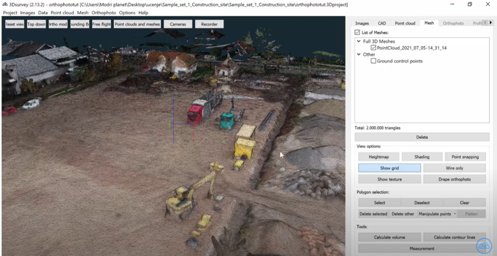
The next thing we need to do is calculate our 3D mesh. First click on the “Mesh” in the upper selection menu and select “Calculate New Full 3D Mesh.” Next, we choose the point cloud we want to use for the mesh calculation (if we have multiple). Make sure to check the “Textured Mesh” box before clicking “Calculate.” This process may take up to 10 minutes. Once the 3D mesh is calculated, we can rotate it by holding the left mouse button and dragging or zoom in by double-clicking or using a scroll wheel. To view the triangles from which the mesh is made, click the “Show Grid” button.


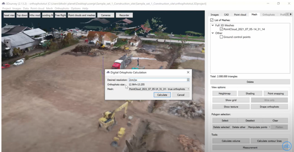
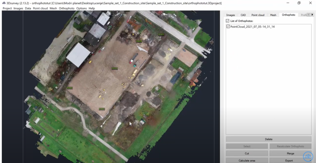
To create an orthophoto, click “Orthophoto” in the upper selection menu and select “Calculate New (Top-down)”. Choose the resolution you want and select the mesh you want to create the orthophoto from (if you have multiple). Click “Calculate” and wait for the process to complete. Once done, we can see our true orthophoto. Everything should be in the correct position, including houses, holes, targets, etc. To view the coordinates of the cursor on the orthophoto, check the bottom left corner. That’s all for this tutorial.

